
HESPER
Choosing a Bellow Compensator in 2026 means looking beyond pipe size and price. The right unit must handle the system’s actual movement, pressure, temperature, media, and operating cycles. A stainless-steel bellows may look robust on a specification sheet, yet poor alignment or an overlooked anchor load can shorten its service life. Small details matter.
The Expansion Joint Manufacturers Association (EJMA) provides technical guidance for evaluating expansion-joint design and performance. Its guidance can be distilled into one practical rule: select for the real operating conditions, not a single catalogue rating. This is a paraphrase, not a direct quotation from a named individual; no verified expert quotation was provided with the source material. That distinction matters when reliability is the goal.
This guide explains how to compare movement capacity, material compatibility, pressure limits, fatigue life, and installation requirements. It also considers support layout, inspection access, and the consequences of startup or temperature changes. A Bellow Compensator is not a cure for every piping problem. Sometimes the better answer is to revisit the piping layout or anchoring plan. There is no universal best model. Careful selection starts with credible operating data, manufacturer documentation, and a review by a qualified piping engineer. One missed condition can change the choice.
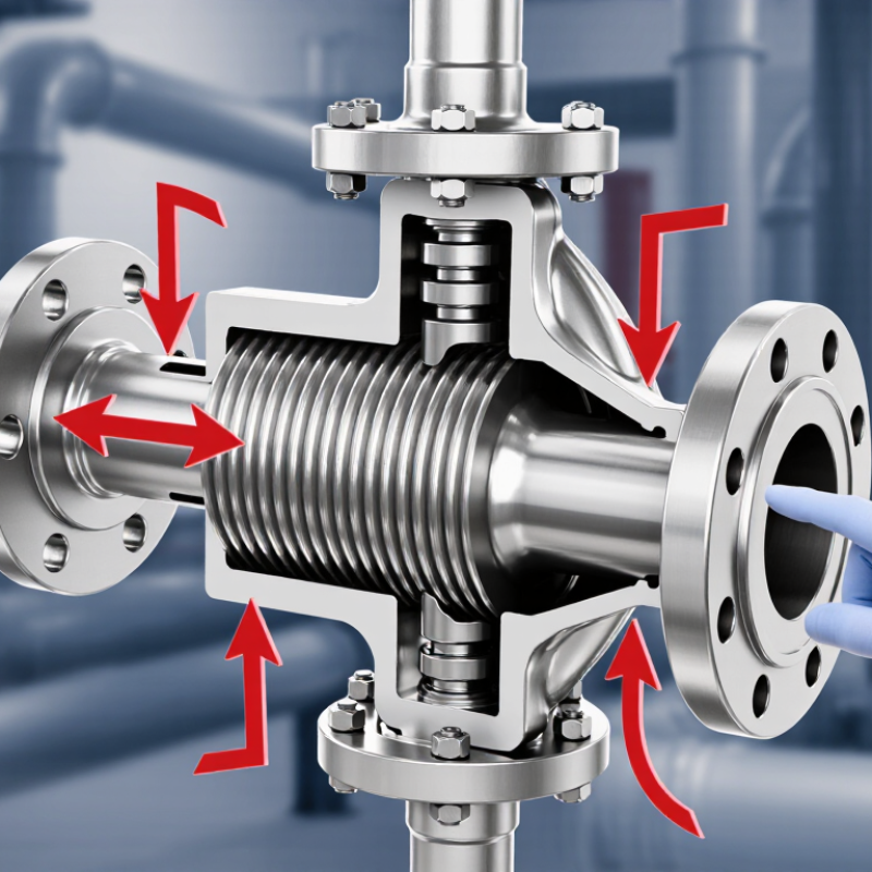
A bellow compensator should match the piping system’s real operating envelope, not just its maximum rating. Record operating and transient pressure, temperature, fluid, pipe material, movement, and cycle frequency. Start-up can create a different load from steady operation. Small details matter: a hot line may move more than expected.
The U.S. Department of Energy’s Improving Steam System Performance: A Sourcebook for Industry estimates that steam accounts for about 30% of U.S. industrial energy use. That makes careful assessment of steam-line movement especially important. For example, a 12-meter carbon-steel pipe heated by 100°C expands roughly 14 millimeters, using a typical expansion coefficient of 12 × 10⁻⁶ per °C. Check the actual material and temperature range; this estimate is not a design value.
Then assess how anchors and guides control that movement, and whether the compensator sees axial, lateral, or angular displacement. Include start-up, shutdown, pressure thrust, vibration, and the expected number of operating cycles. ASME B31.3 provides process-piping design requirements, while EJMA guidance addresses metal-bellows expansion joints. Both help frame the checks, but neither replaces project-specific calculations. A neat drawing can still hide an awkward support layout. Verify it in the field.
Start with movement, not the catalog. Calculate axial growth, lateral offset, and angular rotation from operating and installation temperatures; include pressure, cycle count, and pipe restraint. The Expansion Joint Manufacturers Association’s 11th Edition treats these as core design inputs, while ASME B31.3 provides piping design requirements. For a quick check, a 6 m run of 304 stainless steel heated by 100°C grows roughly 10 mm, using a commonly published expansion coefficient of about 17 × 10⁻⁶/°C. Confirm the coefficient and temperature range against project material data.
Match the movement to the hardware. An axial unit handles movement along its centerline; a hinged unit controls rotation in one plane. Universal designs can absorb lateral offset, while pressure-balanced designs help limit pressure thrust on connected equipment. A neat catalog match can still fail if guides, anchors, or movement combinations are overlooked. I have seen the movement calculation treated as a single number; real pipe runs are less tidy.
Tips: Sketch the anchors and guides, then mark hot and cold positions. Compare the required movement with the manufacturer’s rated capacity, including tolerances. If lateral and axial movement occur together, ask for a combined-movement check—not separate capacity figures.
For a bellow compensator, match the alloy to the actual fluid, not just its name. Record concentration, contaminants, cleaning chemicals, and temperature swings. Chlorides can pit stainless steel, while acids and caustics need different resistance checks. ASTM A240/A240M sets a maximum carbon content of 0.030% for 316L stainless steel. That helps limit sensitization after welding, but it does not make 316L suitable for every chloride service. A neat material chart can still mislead.
Pressure and temperature must be assessed together. ASME B31.3 provides material-specific allowable stresses across temperature ranges; a room-temperature pressure rating is not enough. EJMA’s Standards also treat pressure, movement, and fatigue as connected design inputs. Share operating pressure, vacuum conditions, peak temperature, and expected movement with the manufacturer. Include start-up surges, too. They are easy to overlook. Confirm the selected material and construction against the actual duty, since a bellow’s thin convolutions may respond differently from nearby pipe.
Tips: For a hot chloride wash, check concentration and peak temperature before choosing stainless steel. For uncertain media, ask for written compatibility data and review the assumptions. A small detail can change the answer.
Choosing a bellows compensator starts with the real operating envelope, not the nominal pipe size. Record pressure, temperature, fluid, and the maximum axial, lateral, and angular movement. Include startup, shutdown, and occasional pressure surges. A unit that fits on paper may exceed its limits after thermal growth or installation misalignment. Small details matter.
Fatigue life depends on movement range and expected operating cycles. Estimate cycles across the service period, including frequent temperature changes and process trips. Ask for the calculation basis and confirm that it matches your installation. Corrosion, vibration, and uneven support can shorten service life. I would be cautious about treating a cycle rating as a guarantee; field conditions rarely stay perfectly tidy.
Check the rated pressure and temperature together, since allowable pressure can change as temperature rises. Review the specified safety factors, design code, and test records with a qualified engineer. Also confirm that anchors and guides can handle the loads generated by the compensator. A strong component cannot fix weak supports. Leave room for inspection, and verify face-to-face length before ordering. If key inputs are uncertain, state that uncertainty rather than hiding it in a calculation.
How to Choose a Bellow Compensator in 2026?
Plan Installation, Anchoring, and Ongoing Inspection
Choosing a bellow compensator starts with the movement it must absorb. Confirm operating temperature, pressure, fluid, pipe size, and expected axial or lateral travel. Then check the manufacturer’s design data against the actual system conditions. A component selected only by diameter may not handle the full movement or pressure range. Small details matter.
Plan anchors, guides, and supports before installation. Fixed anchors control where thermal expansion goes; guides keep the pipe moving along its intended path. Check drawings and site measurements together, because a neat drawing can still miss a beam, valve, or tight clearance. Avoid forcing misaligned pipe ends into place or twisting the bellows during fit-up. Follow the supplier’s installation instructions, including when to remove shipping restraints. It is easy to overlook one.
Tips: Photograph the installed unit and record its cold position. During scheduled inspections, look for cracks, corrosion, dents, leakage, loose hardware, anchor movement, or new vibration. Compare changes with earlier records, and ask a qualified engineer to assess unusual movement before it becomes a failure.
| Planning dimension | Example project data | Selection and design action | Installation, anchoring, and inspection checks |
|---|---|---|---|
| Operating service | Hot-water supply line; 150 mm nominal pipe size; carbon-steel piping. | Confirm the fluid, concentration, cleanliness, operating pressure, temperature, and any upset conditions. Select bellows materials and construction for the complete service envelope. | Check that the installed unit’s identification and material documentation match the approved design and the actual service. |
| Temperature and pressure | Normal operation: 90°C and 10 bar; design conditions: 120°C and 16 bar. | Use the design pressure and temperature, not just normal operating values, when checking the compensator’s rated limits. Account for pressure-temperature effects on movement capacity. | Verify pressure and temperature ratings before installation. Record operating conditions during commissioning and compare them with the design basis. |
| Thermal movement | For a 30 m steel run heated by 80°C, estimated free expansion is about 29 mm, using a thermal expansion coefficient of 12 × 10−6/°C. | Calculate movement from the actual pipe material, effective length, temperature range, and system layout. Distribute movement among appropriately located compensators where required. | Confirm that guides and anchors direct the calculated movement into the compensator. Check that the bellows is not compressed, extended, or offset beyond its approved installation setting. |
| Movement direction | Axial movement expected; small lateral movement may occur at a change in direction. | Identify whether the duty is axial, lateral, angular, or a combination. Select a configuration rated for the calculated movement in each direction; do not assume one movement type can substitute for another. | Check alignment, guide locations, and installation length. Look for evidence of twisting, bowing, or contact with nearby steelwork. |
| Pressure thrust and anchoring | At 10 bar, an illustrative 150 mm internal-diameter area produces pressure thrust of approximately 18 kN (pressure multiplied by effective area). | Calculate thrust using the compensator’s effective area and applicable design pressure. Include bellows spring forces, pipe friction, weight, and other relevant loads when designing anchors and supports. | Verify anchor and support details against the approved structural and piping calculations. Do not rely on the compensator or adjacent equipment to restrain pressure thrust unless specifically designed for it. |
| Guides and supports | Long straight run with a fixed anchor at each movement section and intermediate pipe guides. | Lay out anchors and guides to control the intended movement and prevent lateral instability. Follow the compensator design documentation for guide spacing and support arrangement. | Check that guides are secure, correctly aligned, and free to perform their intended function. Confirm that supports do not bind or impose unintended loads on the bellows. |
| Installation condition | Compensator delivered with temporary shipping restraints and protective covers. | Follow the approved installation instructions for orientation, flow direction where applicable, required pre-setting, and removal of restraints. Protect the bellows from welding spatter, debris, and impact. | Remove shipping restraints only at the specified stage. Before startup, check welds or flanges, alignment, cleanliness, and that no temporary restraint remains in service unintentionally. |
| Commissioning baseline | Record operating pressure, temperature, visible alignment, and the compensator’s installed length after startup. | Compare commissioning conditions and movement with the design assumptions. Investigate unexpected movement, vibration, or pressure fluctuations before continued operation. | Keep dated photographs and readings as a baseline for later inspections. Confirm that guards or insulation do not prevent safe inspection access. |
| Routine inspection | Visual inspection at planned maintenance intervals; frequency adjusted for service severity and site risk. | Set inspection intervals based on operating conditions, consequences of failure, duty cycle, and applicable site requirements rather than using a universal interval. | Look for cracks, corrosion, dents, bulging, leakage, unusual discoloration, damaged covers, loose supports, anchor movement, or changes in alignment. Record findings and trends. |
| Maintenance and replacement | Leakage, visible damage, unexpected permanent deformation, or repeated abnormal vibration. | Assess the cause before replacement; check for overpressure, excessive movement, misalignment, unsupported pipe loads, or incorrect anchoring. Use qualified engineering review for corrective changes. | Isolate and depressurize the line before work. Do not weld, straighten, or repair a bellows assembly unless an approved repair procedure specifically permits it. |
Design note: Example values are for planning illustration only. Final selection, movement limits, anchor loads, guide spacing, and inspection requirements must be confirmed using project calculations, the compensator’s approved technical data, and applicable codes.
Record pressure, temperature, fluid, pipe material, movement, and expected operating cycles. Include start-up and shutdown conditions; steady operation is not the whole story.
Start-up surges can create different loads from normal operation. Vibration and pressure thrust also affect the compensator.
A 12-meter carbon-steel pipe may expand about 14 millimeters when heated by 100°C. Treat this as an estimate, not a design value. Real conditions vary.
Check whether movement is axial, lateral, or angular. Review how anchors and guides direct it.
Match the alloy to fluid concentration, contaminants, cleaning chemicals, and temperature swings. Chlorides can pit stainless steel. Acid and caustic services need separate checks.
No. Its low carbon content can help limit weld-related sensitization, but it does not guarantee chloride resistance. Check actual concentration and peak temperature.
Material strength can change with temperature, so room-temperature pressure ratings may mislead. Include vacuum conditions, peak temperature, and start-up surges.
Confirm material, construction, movement, and fatigue assumptions for the real duty. Inspect supports in the field; drawings can look tidy and still hide a poor layout.
Choosing a Bellow Compensator in 2026 starts with understanding the piping system and the conditions it must handle. Consider the operating pressure and temperature, the conveyed medium, and how the pipework behaves during normal operation and temperature changes. Then identify the direction and amount of movement to be accommodated, such as axial, lateral, or angular movement, and select a compensator configuration suited to those requirements.
Next, choose materials compatible with the pressure, temperature, and medium, and check that the design limits, expected fatigue life, and safety factors match the intended service. A suitable compensator also depends on proper installation: plan anchoring and guides, allow for the specified movement, and follow practical inspection and maintenance procedures. Reviewing these factors together helps ensure the selected unit fits the system and performs reliably over its expected operating life.
